Arduino
Arduino Programming
Introduction to Arduino:
So what is Arduino? It is an open-source electronics platform based on easy-to-use hardware and software, used for building electronics projects. Open-source may sound like a foreign word but its meaning is quite simple, all it actually means is that its source code is made freely available for possible modification and redistribution.
Maker Uno Kit
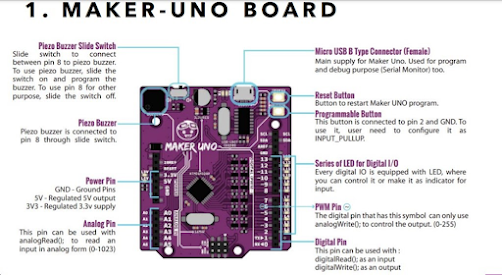
The maker uno board consists of 10 different parts. It has
Piezo Buzzer slide switch
Piezo Buzzer
Power Pin
Analog Pin
Micro USB B Type connector
Rest Button
Programmable Button
Series of LED for Digital I/O
PWM Pin
Digital Pin
This is the cable that comes with the Maker-Uno kit and is used to connect the Maker-Uno board to a computer or laptop with Arduino programming installed. Code can then be made with the program and once the code has been uploaded, the USB cable can be plugged in to any power source for it to perform the uploaded command.

Figure 2: USB Cable

Figure 3: Jumper Wires
Jumper wires are used to connect electrical components to the Maker-Uno Board. They come in many different colours so it is easier to organise them when wiring up.
Documentation of programmed arduino boards and explaining the program codes used
We had to do 4 tasks to get us to understand and learn simple arduino programming. The 4 tasks were :Hello World! ; Programmable button ; Make some noise! ; Servo
Activity 1: Hello World
The goal of this activity is to make one of the LEDs on the Maker-Uno Board blink. It can be accessed in the Arduino Programming software under File > Examples > 01. Basics > Blink.
The code used is shown below:
/*
Blink
Turns an LED on for one second, then off for one second, repeatedly.
Most Arduinos have an on-board LED you can control. On the UNO, MEGA and
ZERO
it is attached to digital pin 13, on MKR1000 on pin 6. LED_BUILTIN is set to
the correct LED pin independent of which board is used.
If you want to know what pin the on-board LED is connected to on your Arduino
model, check the Technical Specs of your board at:
https://www.arduino.cc/en/Main/Products
modified 8 May 2014
by Scott Fitzgerald
modified 2 Sep 2016
by Arturo Guadalupi
modified 8 Sep 2016
by Colby Newman
This example code is in the public domain.
https://www.arduino.cc/en/Tutorial/BuiltInExamples/Blink
*/
// the setup function runs once when you press reset or power the board
void setup() {
// initialize digital pin LED_BUILTIN as an output.
pinMode(LED_BUILTIN, OUTPUT);
}
// the loop function runs over and over again forever
void loop() {
digitalWrite(LED_BUILTIN, HIGH); // turn the LED on (HIGH is the voltage level)
delay(1000); // wait for a second
digitalWrite(LED_BUILTIN, LOW); // turn the LED off by making the voltage LOW
delay(1000); // wait for a second
}
This code will cause the LED light at pin 13 to turn on and off at 1-second intervals.
In the code above, void setup(){} is where the board's pin identity is set up. For example, we can set PIN13 as an input or output, or simply make blink on the board's built-in LED light. void loop(){}is the part where we want the code to run on an infinite loop.
Activity 2: Programmable Button
This activity is to make the LED at pin 13 will light up when the programmable button is pressed, and go off once the button is no longer being pressed. Once the button is not pressed, the LED at pin 2 will light up permanently until the button is pressed again. It can be accessed under File > Examples> 02. Digital > DigitalInputPullup.
The code used is shown below:
/*
Input Pull-up Serial
This example demonstrates the use of pinMode(INPUT_PULLUP). It reads a digital
input on pin 2 and prints the results to the Serial Monitor.
The circuit:
- momentary switch attached from pin 2 to ground
- built-in LED on pin 13
Unlike pinMode(INPUT), there is no pull-down resistor necessary. An internal
20K-ohm resistor is pulled to 5V. This configuration causes the input to read
HIGH when the switch is open, and LOW when it is closed.
created 14 Mar 2012
by Scott Fitzgerald
This example code is in the public domain.
https://www.arduino.cc/en/Tutorial/BuiltInExamples/InputPullupSerial
*/
void setup() {
//start serial connection
Serial.begin(9600);
//configure pin 2 as an input and enable the internal pull-up resistor
pinMode(2, INPUT_PULLUP);
pinMode(13, OUTPUT);
}
void loop() {
//read the pushbutton value into a variable
int sensorVal = digitalRead(2);
//print out the value of the pushbutton
Serial.println(sensorVal);
// Keep in mind the pull-up means the pushbutton's logic is inverted. It goes
// HIGH when it's open, and LOW when it's pressed. Turn on pin 13 when the
// button's pressed, and off when it's not:
if (sensorVal == HIGH) {
digitalWrite(13, LOW);
} else {
digitalWrite(13, HIGH);
}
}
In the code, when the IF condition is met, the Maker-Uno Board will execute an action. If the condition is not met it will follow the ELSE action. In this case, IF sensorVal status is HIGH, PIN13 will be LOW, ELSE, it will be HIGH. This means that if the button is not pressed, the light will be off which is represented by low and if the button is press the light will on represented by high.
Activity 3: Make Some Noise
The goal of the activity is to make the Maker-Uno Board play a quick melody on the Piezo Buzzer. It can be accessed under File > Examples> 02. Digital > toneMelody.
The code used is shown below:
/*
Melody
Plays a melody
circuit:
- 8 ohm speaker on digital pin 8
created 21 Jan 2010
modified 30 Aug 2011
by Tom Igoe
This example code is in the public domain.
https://www.arduino.cc/en/Tutorial/BuiltInExamples/toneMelody
*/
#include "pitches.h"
// notes in the melody:
int melody[] = {
NOTE_C4, NOTE_G3, NOTE_G3, NOTE_A3, NOTE_G3, 0, NOTE_B3, NOTE_C4
};
// note durations: 4 = quarter note, 8 = eighth note, etc.:
int noteDurations[] = {
4, 8, 8, 4, 4, 4, 4, 4
};
void setup() {
// iterate over the notes of the melody:
for (int thisNote = 0; thisNote < 8; thisNote++) {
// to calculate the note duration, take one second divided by the note type.
//e.g. quarter note = 1000 / 4, eighth note = 1000/8, etc.
int noteDuration = 1000 / noteDurations[thisNote];
tone(8, melody[thisNote], noteDuration);
// to distinguish the notes, set a minimum time between them.
// the note's duration + 30% seems to work well:
int pauseBetweenNotes = noteDuration * 1.30;
delay(pauseBetweenNotes);
// stop the tone playing:
noTone(8);
}
}
void loop() {
// no need to repeat the melody.
}
This will cause the buzzer to play a quick melody.
In the code above, #include "pitches.h" refers to the inclusion of all the pitches in a library so that the code can refer to the library when the code is being called. int melody[] is an array where integer information are stored in melody array. Similar to melody, int noteDurations[] stores the information of the note duration.
Activity 4: Servo
The goal of this activity is to make the rotor blade of a servo motor that is connected to the Maker-Uno Board spin. It can be accessed under File > Examples > Servo > Sweep.
The code used is shown below:
/* Sweep
by BARRAGAN <http://barraganstudio.com>
This example code is in the public domain.
modified 8 Nov 2013
by Scott Fitzgerald
https://www.arduino.cc/en/Tutorial/LibraryExamples/Sweep
*/
#include <Servo.h>
Servo myservo; // create servo object to control a servo
// twelve servo objects can be created on most boards
int pos = 0; // variable to store the servo position
void setup() {
myservo.attach(9); // attaches the servo on pin 9 to the servo object
}
void loop() {
for (pos = 0; pos <= 180; pos += 1) { // goes from 0 degrees to 180 degrees
// in steps of 1 degree
myservo.write(pos); // tell servo to go to position in variable 'pos'
delay(15); // waits 15 ms for the servo to reach the position
}
for (pos = 180; pos >= 0; pos -= 1) { // goes from 180 degrees to 0 degrees
myservo.write(pos); // tell servo to go to position in variable 'pos'
delay(15); // waits 15 ms for the servo to reach the position
}
}
This section is our individual activity and these are the task that we needed to do with TinkerCAD.

Potentiometer:


The code used:


Comments
Post a Comment